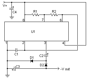
Circuit diagram
Parts
R1 1M Linear Pot
C1,C2 15uf 25V Electrolytic Capacitor
U1 LM380 Audio Amp Chip
MISC Heatsink For U1, Binding Posts (For Input/Output), Wire, Board
Notes
1. U1 dissipates around 1W and will therefore require a heatsink.
2. R1 is used to equalize the outputs. The first time you use the circuit, it should be set to mid range and then adjusted with the aid of a voltmeter. Measure each output while adjusting. The circuit is calibrated when both outputs read the same voltage (either positive or negative).
circuit diagram with IC555
R1=24K 1/4 Watt Resistor
R2=56K 1/4 Watt Resistor
C1=3300pF 25V Ceramic Capacitor
C2=47uF 25V Electrolytic Capacitor
C3=10uF 25V Electrolytic Capacitor
C4=100uF 25V Electrolytic Capacitor
D1,D2=1N4148 Silicon Diode


Tidak ada komentar:
Posting Komentar